

Action unknown: siteexport_addpage
meta data for this page
How an Ironcore Flat Linear Motor Works
Introduction
An ironcore flat linear motor is a direct-drive electric actuator built from two flat components: a primary part (the coil unit) and a secondary part (the magnet track). Like its tubular counterpart, it produces linear motion with no mechanical transmission — but its slotted, laminated architecture gives it the highest force density of all linear motor types, which makes it the first choice for machine tables, gantries and every application where high force must fit into a compact cross-section.
The defining characteristic of the ironcore design is the normal attraction force between the primary and the secondary — a direct consequence of the magnetic circuit passing through iron. Handled correctly in the mechanical design, this is the price paid for a force density and cost efficiency that no other linear motor architecture can match.
The NILAB L/LK/L1S ironcore series delivers continuous forces from 150 N to 7500 N and peak forces from 440 N to 15750 N, in seven primary frame sizes with up to five primary lengths per frame.
Core Components
The Primary Part (Coil Unit)
The primary part is the active component. It consists of a laminated silicon-steel stack with slots carrying the three-phase winding (U, V, W). The laminations concentrate the magnetic flux across the air gap — this is what gives the ironcore motor its high force density.
The complete primary is encapsulated in a protective epoxy resin that is resistant to shock and aggressive substances, so it can operate in harsh industrial environments. A thermal sensor is embedded in the windings (Thermoswitch, PTC, KTY or NTC, depending on the ordering code) and monitored by the servo drive. Power is supplied through a cable with flying leads or a circular connector, with different cable exit directions (X, Y and Z) available.
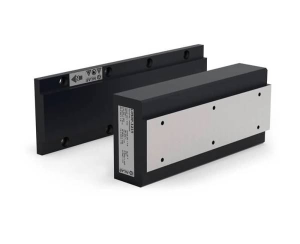
The Secondary Part (Magnet Track)
The secondary part is a flat magnet track: high-energy NdFeB permanent magnets are fixed to a solid steel back iron, which closes the magnetic circuit. The magnets are arranged with alternating polarity at the motor pole pitch τ, matching the slot pattern of the primary.
The track is built from modular segments bolted end-to-end, so the travel can be extended almost arbitrarily by adding segments. Like the primary, the secondary is covered by the protective epoxy resin.
The Linear Encoder
Unlike tubular motors, an ironcore flat motor has no integrated encoder. Position feedback comes from an external linear encoder: a measuring standard mounted along the machine travel, read by a scanning head carried by the primary part. Depending on the feedback system (e.g. the NILAB HSB feedback), incremental 1 Vpp SIN/COS signals or absolute interfaces are available; with interpolation in the servo drive, resolutions in the sub-micron range are achieved.
The Machine Guide and the Air Gap
An ironcore motor has no built-in bearing. The payload is carried by the machine's own linear guide, which must also react the normal attraction force (see below). The primary is mounted above the secondary with a small, precisely defined nominal air gap — the installation tolerances must be respected so that the gap neither closes under the attraction force nor opens excessively under machine deformation.
Operating Principle
Lorentz Force in Slotted Laminations
Force generation follows the Lorentz force law, as in every synchronous linear motor:
F = B · I · L · N
where B is the magnetic flux density [T], I the phase current [A], L the effective conductor length [m] and N the number of turns. The difference to an ironless design is the magnetic circuit: the laminated teeth of the primary concentrate the magnet flux from the secondary across the air gap, so the effective flux density in the slots is much higher than in an air-cored motor. This is why an ironcore motor delivers more force per frame size and per magnet material.
The slotted architecture also introduces cogging (detent force): the teeth tend to align themselves with the magnets even without current. In a well-designed motor the effect is minimised by the slot/pole geometry and by electronic compensation in the servo drive, so the resulting force ripple stays small — but it is inherently higher than in a slotless (tubular) motor.
The Normal Attraction Force
Because the magnetic circuit passes through iron, the primary and the secondary attract each other with a force that is typically several times higher than the rated thrust — and it is present even when the motor is switched off. This attraction force is a permanent load on the linear guides and the machine structure and must be accounted for in every mechanical design.
Practical countermeasures are described on the dedicated page and in motor arrangement: linear guides placed as close to the motor as possible, sufficient structural rigidity, and — where the attraction force becomes an advantage — the double-comb parallel arrangement of two primaries facing each other. The exact value for each motor size is specified in its Technical data sheet at the nominal air gap.
Three-Phase Commutation
Like every brushless synchronous linear motor, the ironcore motor uses three-phase AC commutation (sinusoidal field-oriented control, FOC). The servo drive generates three sinusoidal current waveforms, phase-shifted by 120°, applied to the winding phases U, V and W.
As the primary moves along the track, the linear encoder continuously reports the position to the drive. The drive computes the instantaneous electrical angle (commutation angle) from this position and distributes the current among the three phases so that the current vector stays at 90° to the magnet flux — the condition that maximises force per ampere.
The pole pitch τ defines the spatial period of the commutation cycle: one complete electrical period occurs every 2·τ of travel (e.g. 60 mm for a motor with τ = 30 mm).
Force–Speed Characteristic
The ironcore motor force–speed curve has two regions:
| Item |
| Continuous force (F_cont): the force level that can be sustained indefinitely, limited by the thermal rating of the windings. |
| Peak force (F_peak): typically 2–4× F_cont, available for short duty cycles (acceleration bursts), limited by the drive current capability. |
At higher speeds the back-EMF (the voltage generated by the moving magnets) reduces the current available for force generation, creating the characteristic force roll-off region. The speed at which roll-off begins depends on the supply voltage and the motor back-EMF constant (Ke):
V_max ≈ (V_dc − I·R) / Ke
This is why the correct bus voltage is important when high-speed operation is required.
Thermal Management
The primary heat source is Joule heating (I²·R losses) in the copper windings. Because the primary is bolted directly to the machine structure, a large part of this heat flows straight into the machine body — an excellent heat sink, and one of the practical advantages of the flat architecture. For higher duty cycles the LK series adds an integrated liquid cooling circuit, which substantially increases the available continuous force.
The embedded thermal sensor (Thermoswitch, PTC, KTY or NTC) provides a direct winding-temperature signal to the servo drive, which can raise a warning or trigger a fault before the thermal limit is reached.
Position Feedback and Closed-Loop Control
The servo drive implements a cascaded control loop:
| Item |
| Current loop (innermost): regulates the three-phase currents to follow the force command. Bandwidth: typically 5–10 kHz. |
| Velocity loop: regulates the primary velocity based on encoder-derived speed. Bandwidth: typically 100–500 Hz. |
| Position loop (outermost): regulates the absolute position to the target setpoint. Bandwidth: typically 20–100 Hz. |
The linear encoder signals are interpolated by the drive to achieve resolutions down to the sub-micron range, which makes ironcore flat motors suitable for precision positioning tasks that would be impossible with pneumatic or open-loop actuators.
Ironcore vs Tubular: When to Choose Which
| Parameter | Ironcore flat (L/LK/L1S) | Tubular (ironless) |
| Force density | Highest (flux concentrated by laminations) | High |
| Force ripple | Low, but present (slotted design → cogging) | Very low (< 1%, slotless) |
| Normal attraction force | Present — several × thrust, permanent | None (axially symmetric) |
| Heat dissipation | Large part flows into the machine structure | Through the stator housing |
| Encoder | External linear scale + reading head | Integrated in the motor body |
| Typical applications | Machine tables, gantries, long travels with high force | Cylinder replacement, sealed/vertical axes, clean rooms |
As a rule of thumb: choose the ironcore flat motor when maximum force density and cost-efficient long travels are the priority and the machine structure can carry the attraction force. Choose the tubular motor when zero cogging, no attraction force or a fully integrated, sealed actuator is the priority.
Summary
An ironcore flat linear motor is a three-phase brushless servomotor flattened into a linear primary. A slotted, laminated coil unit runs above a magnet track with a steel back iron; the laminations concentrate the flux, giving the highest force density of any linear motor type at the price of a permanent normal attraction force that the machine design must react. Field-oriented three-phase commutation from a linear encoder closes the control loop to sub-micron position resolution. The result is an extremely force-dense, maintenance-free and energy-efficient actuator for machine tables, gantries and high-force linear axes.