

Action unknown: siteexport_addpage
meta data for this page
Connectors and indicators
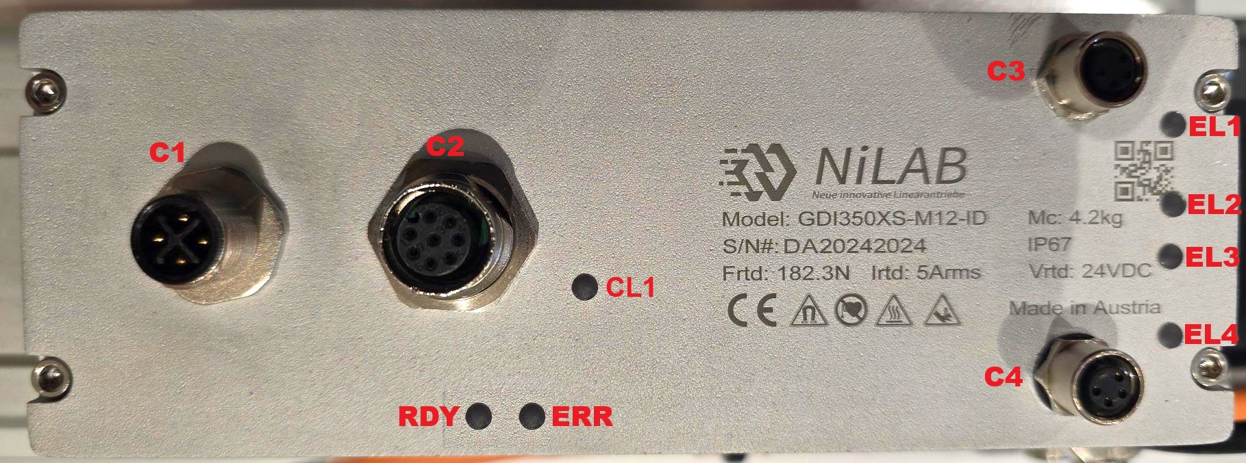
LED Indicators
| Indicators | Function | States | Color |
| CL1 | Control logic | Active - blinking | Blue |
| RDY | EtherCAT Slave status | EtherCAT Ready - LED active PreOP state - LED flashing INIT state - LED off SafeOP - single flash | Green |
| ERR | EtherCAT Slave error status | EtherCAT Configuration Error - LED blinking No Error - LED off Unsolicited State Change - LED single flash Application Watchdog Timeout - LED double flash PDI Watchdog Timeout - LED active | Red |
| EL1 | EtherCAT communication | Active - connection to EtherCAT | Orange |
| EL2 | EtherCAT communication | Blinking - link port activity | Green |
| EL3 | EtherCAT communication | Active - connection to EtherCAT | Orange |
| EL4 | EtherCAT communication | Blinking - link port activity | Green |
Connectors
C1 connector - 24VDC power (M12 A code 4 poles male)
M12 power cable, female A code - DA00027011, with flying leads.
The power cable terminates with two wires: RED (+24VDC), BLACK (GND).

C2 connector - Signal and communication (M12 8 poles female)
Signal cable male DA00012011 with D-SUB 15 male connector
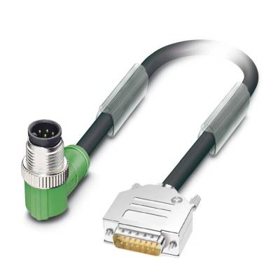
| D-SUB 15 Pinout | SIGNAL | DESCRIPTION | FUNCTION |
| 1 | RS485_B | Modbus B | |
| 2 | RS485_A | Modbus A | |
| 3 | GND | Ground | |
| 4 | NC | Not connected | |
| 5 | NC | Not connected | |
| 6 | GND | Ground | |
| 7 | GND | Ground | |
| 8 | STO1 | Digital Input 0 (24V logic) | Safe torque off |
| 9 | STO2 | Digital Input 1 (24V logic) | Safe torque off |
| 10 | DIG_OUT_0 | Digital output 0 (24V logic, PNP) | Motor running |
| 11 | DIG_OUT_1 | Digital output 1 (24V logic, PNP) | Motor fault |
| 12 | DIG_OUT_2 | Digital output 2 (24V logic, PNP) | Programmable |
C4 connector - EtherCAT IN (M8 4 poles female) DA0002911

C3 connector - EtherCAT OUT (M8 4 poles female) - PATCH CABLE DA0003911
