

Action unknown: siteexport_addpage
meta data for this page
Connection system
This page describes the connection system of the Green Drive ISO tubular linear motor. The motor is connected to the servo drive through the standard Speedtec connectors on the stator side.
Stator side with Speedtec M23 and M17
The table below shows the pin assignment for the two connectors (M17 signal and M23 power).
| PIN | FUNCTION | CONNECTOR VIEW FRONT | PIN | FUNCTION |
| 12 | SIN+/SLO+ | 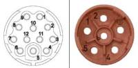 | 1 | U |
| 11 | SIN-/SLO- | 2 | V | |
| 10 | COS+/MA- | Earth | PE | |
| 9 | COS-/MA+ | 4 | - | |
| 8 | PTC-/A- | 5 | - | |
| 7 | PTC+/A+ | 6 | W | |
| 6 | +5VDC | |||
| 5 | GND | |||
| 4 | - | |||
| 3 | -/B- | |||
| 2 | -/B+ | |||
| 1 |
Connectors: Intercontec Speedtec AEDC047NN0000051A000 (M17) + BEDC106NN00000201000 (M23)
Notes
- The M17 connector carries the signal (encoder, PTC, +5V, GND); the M23 connector carries the motor phases (U, V, W) and the earth. - The pin assignment shown is the view from the connector front. - Use the mating connectors listed above; the cable assembly is shown in the cable configuration page. - For the wiring of the other connector types (M15/Ytec for smaller motors), refer to the cable configuration page.