

Action unknown: siteexport_addpage
meta data for this page
Thermal Sensor
L/LK series ironcore flat linear motors monitor the winding temperature with PTC thermistor sensors embedded in the windings. This page describes the sensor configuration of the series, its resistance–temperature characteristic and the threshold values to be set in the PLC for warning, alarm and hardware backup trip.
Related pages: L/LK ironcore series · Connection system · How an ironcore flat linear motor works
Sensor configuration
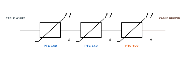
The sensor chain consists of two PTC140 and one PTC600 thermistors connected in series, embedded in the motor windings:
- PTC600 — monitors the winding temperature across the whole operating range (gradual resistance rise with temperature).
- 2 × PTC140 — hardware backup: sharp resistance step at ≈ 140 °C, independent of any drive software.
Since the three elements are connected in series, the measured resistance is the sum of the three contributions: the PLC reads a single value and discriminates all three protection levels by threshold.
| Wire | Colour |
|---|---|
| Protective ground | yellow–green |
| PTC chain (2× PTC140 + 1× PTC600) | white / brown |
Resistance vs temperature
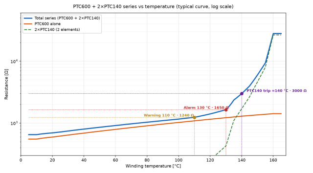
The characteristic is non-linear by design:
- up to ≈ 130 °C the total resistance rises gradually (the PTC600 dominates: ≈ 480 Ω at 10 °C → ≈ 1450 Ω at 160 °C);
- at ≈ 140 °C the two PTC140 trip, multiplying the total resistance by more than an order of magnitude (from ≈ 3000 Ω to > 20 kΩ within a few kelvin).
This is what allows the same pair of wires to carry three different protection levels.
In practice, the curve shows a linear trait up to ≈ 115 °C of winding temperature — the curve is the PTC600 one, which dominates the series. Beyond that temperature the 2 × PTC140 come into play: their characteristic is switch-like and the total resistance rises very rapidly.
Measuring device configuration
The configuration refers to the analog input of a Siemens ET 200SP station — module 6ES7134-6JD00-0CA1 (AI 4xRTD/TC 2-/3-/4-wire HF).
The ET 200SP is Siemens' modular distributed I/O system: the I/O station is mounted next to the machine and connects to the controller via PROFINET. The 6ES7134-6JD00-0CA1 is its 4-channel high-feature analog input for thermal resistors (RTD), thermocouples, resistors and voltage — resolution up to 16 bits, with per-channel measurement type, interference frequency suppression and smoothing, plus per-channel diagnostics.
Configure the analog input as follows:
| Parameter | Setting |
|---|---|
| Measurement type | Resistor (2-wire) |
| Measuring range | 6000 Ω |
| Interference suppression | 50 Hz |
| Smoothing | medium or high |
Do not use the “PTC” mode: it is designed for Kaltleiter type A according to DIN/VDE 0660-302, i.e. for a single trip. For this chain the ohm reading with the 6000 Ω range is required — it also returns the linear part of the characteristic.
PLC thresholds
| Level | Temperature | Typical series R | PLC threshold | Re-entry hysteresis |
|---|---|---|---|---|
| Warning | 110 °C | ≈ 1240 Ω | 1240 Ω | 1200 Ω |
| Alarm | 130 °C | ≈ 1650 Ω | 1650 Ω | 1550 Ω |
| PTC140 trip (hardware backup) | ≈ 140 °C | ≈ 3000 Ω | 3000 Ω | 1800 Ω |
- Warning — 1240 Ω (≈ 110 °C): the winding is approaching the thermal limit. Reduce the load or improve the cooling. The signal resets automatically when the resistance falls below 1200 Ω.
- Alarm — 1650 Ω (≈ 130 °C): the thermal limit is reached. Stop the drive or force the derating. Resets below 1550 Ω.
- Hardware backup — 3000 Ω (≈ 140 °C): the PTC140 pair has tripped. This level is independent of any software setting — the resistance step is generated by the sensors themselves. Resets below 1800 Ω only after cooling down.
PLC logic (Structured Text)
R := INT_TO_REAL(raw) * 6000.0 / 27648.0;   // 6000 Ω range
IF raw >= 32000 OR R < 300.0 THEN           // overrange / broken wire / short
    fault := TRUE;                           // sensor fault, not a temperature fault
END_IF;
// debounce approx. 2 s, then:
IF R >= 1240.0 THEN warn  := TRUE; END_IF;
IF R <= 1200.0 THEN warn  := FALSE; END_IF;
IF R >= 1650.0 THEN alarm := TRUE; END_IF;
IF R <= 1550.0 THEN alarm := FALSE; END_IF;  // manual reset is preferable
The raw value is scaled on the 6000 Ω range (27648 = nominal full scale of a Siemens-type analog input). The sensor fault (overrange, broken wire or short circuit) is reported separately from the temperature levels: it must not be confused with a thermal alarm. The alarm is better handled with a manual reset from the HMI.
Implementation notes
- Evaluate the chain with a single analog input: the three levels are discriminated by threshold on the total resistance.
- Set the re-entry hysteresis exactly as in the table to avoid warning/alarm chatter around the thresholds.
- The PTC140 trip (3000 Ω) is a hardware protection: before reset, check the wiring — a broken lead reads as an open circuit.
- Resistance values are typical values: configure the PLC thresholds on the figures of the table, not on the individual sensor datasheets.