

meta data for this page
How a Tubular Linear Motor Works
Introduction
A tubular linear motor is a direct-drive electric actuator: it produces linear motion with no mechanical transmission. A conventional servo motor needs a gearbox, lead screw, or belt to convert rotation into translation. A tubular linear motor instead generates force directly along the axis of movement. The result is a system with zero backlash, high dynamic response, and virtually no mechanical wear.
NILAB tubular linear motors are used in a wide range of industrial applications: pick-and-place systems, press and forming machines, dispensing, medical equipment, semiconductor handling, and as direct replacements for pneumatic cylinders.
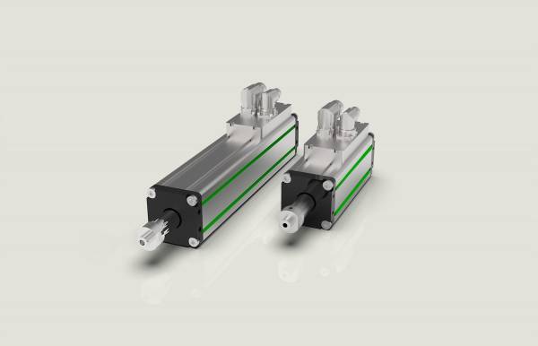
Core Components
A tubular linear motor consists of two main parts — a fixed stator and a moving magnet rod — plus an integrated encoder.
The Stator (Coil Assembly)
The stator is the fixed, outer housing. It contains a set of copper windings arranged in three phases (U, V, W). These windings are distributed along the axis in a spatial pattern whose pole pitch matches the magnet arrangement of the moving rod. The stator is effectively the winding assembly of a rotary motor “unrolled” and wrapped around a cylinder.
The stator housing is usually made of aluminium alloy for effective heat dissipation. A PTC (Positive Temperature Coefficient) sensor is embedded in the windings and monitored by the servo drive to prevent overheating.
The Forcer / Mover (Magnet Rod)
The moving part is a cylindrical rod containing a series of permanent magnets in alternating polarity along its length. High-energy NdFeB (Neodymium-Iron-Boron) magnets are typically used to achieve high force density in a compact diameter.
The magnet rod slides axially inside the stator bore with a very small air gap. It is the only moving mechanical element — no ball screws, no belts, no gears. End caps and rod seals protect the interior from contamination in industrial environments.
The Integrated Encoder
Position feedback comes from an encoder integrated directly into the motor body. In NILAB motors this is a high-resolution SIN/COS incremental encoder (1 Vpp signal), which delivers sub-micron resolution when combined with a servo drive interpolator.
The encoder PCB is fixed inside the stator and detects the magnetic field from the rod. This arrangement provides position information within one motor stroke, without external linear scales. Some models (BISS-C option) support absolute multi-turn serial encoders, allowing instant position readout after power-on without a homing cycle.
The Anti-Rotation Mechanism
Because the stator produces a pure axial force, the magnet rod is free to rotate unless constrained. For applications where the rod must not spin — for example when carrying a guided payload — NILAB motors provide an anti-rotation accessory: typically a keyway sleeve or an external linear guide that prevents rotation while allowing free axial travel.
Operating Principle
Lorentz Force — From Current to Linear Motion
The operating principle is the Lorentz force law: a current-carrying conductor in a magnetic field experiences a force perpendicular to both the current direction and the magnetic field vector.
In a tubular motor, current flows circumferentially through each winding coil, and the permanent magnets on the rod create a radial magnetic field. The interaction produces an axial (thrust) force. By controlling the magnitude and direction of the current in each phase, the servo drive controls both the amplitude and the direction of the linear force.
The theoretical peak force F [N] for a single coil is:
F = B · I · L · N
where B is the magnetic flux density [T], I the phase current [A], L the effective conductor length [m], and N the number of turns per coil. In a real motor, the total force is the sum of the contributions from all active coils carrying current simultaneously.
Three-Phase Commutation
Like a brushless rotary servomotor, a tubular linear motor uses three-phase AC commutation (sinusoidal field-oriented control, or FOC). The servo drive generates three sinusoidal current waveforms, phase-shifted by 120°, applied to the three winding phases U, V, W.
As the magnet rod moves, the encoder continuously reports position to the drive. The drive uses this position to compute the instantaneous electrical angle (commutation angle), which determines how much current flows in each phase at every instant. This keeps the stator current vector at 90° to the rotor flux — the condition that maximises force per amp.
The motor pole pitch (τ) defines the spatial period of the commutation cycle. For a motor with pole pitch τ = 60 mm, one complete electrical period occurs every 60 mm of linear travel.
Force–Speed Characteristic
The tubular linear motor force–speed curve has two regions:
| Item |
| Continuous force (F_cont): the force level that can be sustained indefinitely, limited by the thermal rating of the windings. |
| Peak force (F_peak): typically 2–4× F_cont, available for short duty cycles (acceleration bursts), limited by drive current capability. |
At higher speeds, back-EMF (the voltage generated by the moving magnets) reduces the available current for force generation, creating a characteristic force roll-off region. The speed at which roll-off begins depends on the supply voltage and the motor's back-EMF constant (Ke).
The relationship between peak velocity, supply voltage, and motor parameters is:
V_max ≈ (V_dc − I·R) / Ke
This is why selecting the correct bus voltage is important when high-speed operation is required.
Position Feedback and Closed-Loop Control
The servo drive implements a cascaded control loop:
| Item |
| Current loop (innermost): regulates the three-phase currents to follow the force command. Bandwidth: typically 5–10 kHz. |
| Velocity loop: regulates the rod velocity based on encoder-derived speed. Bandwidth: typically 100–500 Hz. |
| Position loop (outermost): regulates the absolute position of the rod to the target setpoint. Bandwidth: typically 20–100 Hz. |
The SIN/COS encoder signals are interpolated by the drive to achieve resolutions in the range of 0.1 µm to 1 µm, depending on the interpolation factor. This makes tubular linear motors suitable for precision positioning tasks that would be impossible with pneumatic or open-loop electric actuators.
Thermal Management
The primary source of heat in a tubular linear motor is Joule heating (I² · R losses) in the copper windings. At continuous operation, the stator housing must dissipate this heat to the environment or to a cooling circuit.
NILAB motors are rated for continuous operation up to a winding temperature of 130°C (Class F insulation). The aluminium housing conducts heat outward, and convective cooling is usually sufficient for moderate duty cycles.
For high duty-cycle or high-force applications, forced air cooling (an axial fan blowing over the stator fins) or liquid cooling (a water jacket around the stator) are available. Liquid cooling can increase the continuous force rating by a factor of 2–3× compared to natural convection.
The PTC sensor in the windings provides a direct winding-temperature signal to the servo drive, which can trigger a warning or fault before the thermal limit is reached.
Advantages Over Traditional Actuators
| Parameter | Tubular linear motor | Pneumatic Cylinder | Ball screw Actuator |
| Force ripple | Very low (< 1%) | Moderate | Low |
| Positioning accuracy | ±0.1 mm | No position control | ±10 µm or less |
| Speed | Up to 5 m/s | Up to 2–3 m/s | Up to 1 m/s |
| Mechanical backlash | Zero | Not applicable | 0.02–0.1 mm |
| Maintenance | None (no wear parts) | Seals, filter, lubrication | Lubrication, nut wear |
| Energy efficiency | High | Low (15–20%) | High |
| Programmable force profile | Yes (full) | No | Indirect (via current limit) |
| Noise level | Very low | High (exhaust) | Moderate |
Summary
A tubular linear motor is essentially a three-phase brushless servomotor unrolled into a straight line. Permanent magnets on a rod travel axially inside a wound stator, driven by Lorentz forces generated by field-oriented current control. An integrated encoder closes the loop to the servo drive, enabling precise position, velocity, and force control with no mechanical transmission losses. The result is a highly dynamic, maintenance-free, and energy-efficient alternative to pneumatic cylinders and electromechanical screws.