

meta data for this page
Connections
MODBUS RTU only
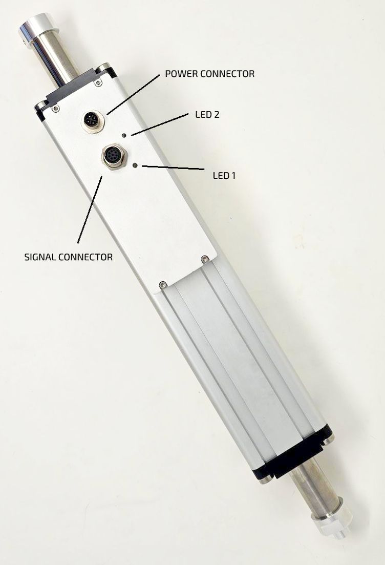
LED Indicators
| LED | Color | Description / Function |
| LED 1 | Green | Power - pulsing when motor is in no fault |
| LED 2 | Red | Blinking when in MODBUS communication with PLC or NILAB Starter - fixed when the motor is in fault |
Cables
The GDI integrated drive motor is equipped with two M12 connectors.
The power connector uses a power female cable DA00022011 with flying leads, and the signal connector uses a signal male cable DA00012011.
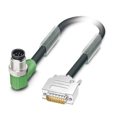 | 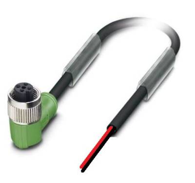 |
| Signal cable DA00012011 | Power cable DA022022 |
The signal cable DA00012011 terminates with a D-SUB 15 male connector with this pinout:
| D-SUB 15 Pinout | SIGNAL | DESCRIPTION | FUNCTION |
| 1 | RS485_B | Modbus B | |
| 2 | RS485_A | Modbus A | |
| 3 | GND | Ground | |
| 4 | NC | Not connected | |
| 5 | NC | Not connected | |
| 6 | GND | Ground | |
| 7 | GND | Ground | |
| 8 | DIG_IN_0 | Digital Input 0 (24V logic) | Enable/Homing |
| 9 | DIG_IN_1 | Digital Input 1 (24V logic) | Motion trigger |
| 10 | DIG_OUT_0 | Digital output 0 (24V logic, PNP) | Motor running |
| 11 | DIG_OUT_1 | Digital output 1 (24V logic, PNP) | Motor fault |
| 12 | DIG_OUT_2 | Digital output 2 (24V logic, PNP) | Programmable |
The programmable outputs have the following options: In Position, Homing in progress, Overtemp fault, sin/cos fault, I2T fault, Master sync, gripper command. This is programmable with NILAB Starter software.