

meta data for this page
Installation procedure
How to handle the rod
Please use proper gloves to handle the sliders.
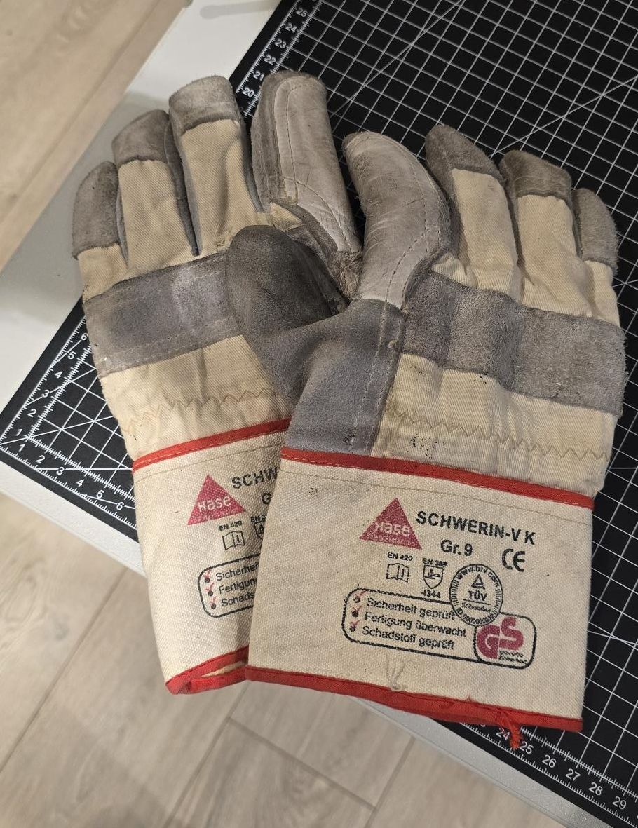
There is a strong magnetic field on the slider: When not packaged, please store the slider at a safe distance!
A minimum distance of 15 cm between the rods, or between the rod and any metallic materials around the mounting area, must be maintained.
Use wood as support material to store the rods without packaging. When mounted near metallic parts, use wood as a spacer for mounting.
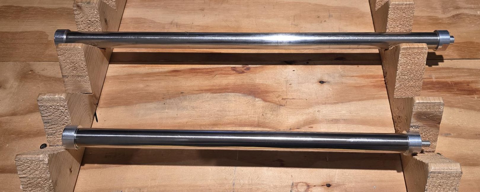
To decouple the two rods joined by attraction force, first rotate one slider by 90 degrees to reduce the force, and then complete the decoupling by applying the necessary separation force.
How to mount the rod inside the motor
The slider of the motor is supplied in a separate carton tube to avoid damage during transportation. This slider has an end stop without threaded holes (male or female) on the closed side.

To install, the customer must open the open side; the grub screws must be unscrewed.

Then follow these steps:
| Item |
| Dismount completely the end cap |
| Insert the slider inside the motor |
| Mount again the end stop on the internal screw of the slider |
| Close completely the end cap, reaching the stainless steel rod end |
| Screw the grub screws to prevent the end cap from rotating |


Interaction with the load
The slider motion is based on polymer plain bearings. The motor slider can only sustain limited radial loads, so the payload must be supported through a proper linear guide. Moreover, coupling the shaft to the payload by spherical bearings, articulated joints, or equivalent parts is recommended, in order to transmit only the linear thrust and to compensate any radial misalignment.

Magnetic fields
The slider of the green drive linear motor is fitted with strong permanent magnets that are not magnetically shielded (Br ≈ 1.2 T). However, the magnetic induction collapses within 50 mm, so there is no significant field outside the machine structure.
Vibrations and shocks
The stator of Green Drive series tubular linear motors can sustain shocks up to 5 G (49 m/s²) and vibrations up to 2.5 G (24.5 m/s²).
Noise emission
The noise emission of synchronous linear drives can be compared with conventional inverter-operated feed drives. Experience has shown that the noise generation mainly depends on:
| Item |
| the employed linear guides (velocity-related travel noise) |
| the mechanical design (following cover, etc.) |
| the settings of drive and controller (e.g. switching frequency) |
A generally valid specification is therefore not possible.