

meta data for this page
Elmo Servo Drive
Installation with Elmo Gold DC Bell
Feedback
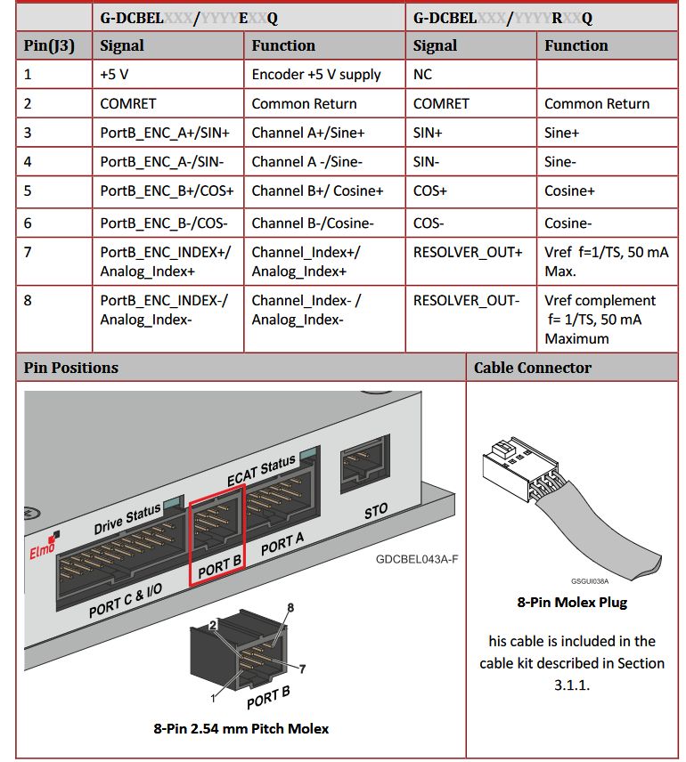
The motor feedback must be connected to the feedback port (DC Bell in port B) with the adapter cable with code DA002030-1M.
Motor phases
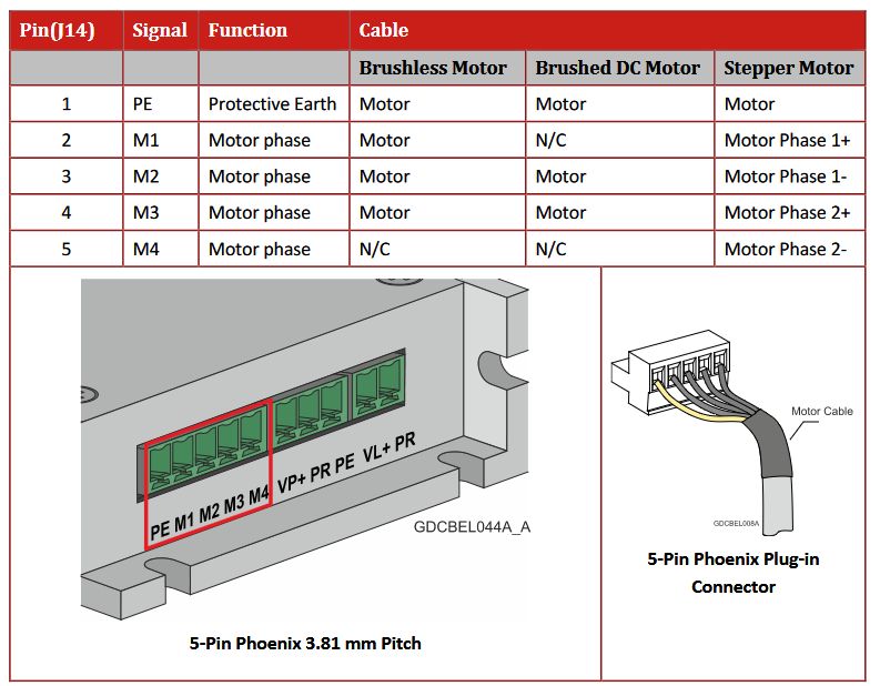
M1, M2, and M3 must be connected respectively to the U, V, and W phases of the linear motor. Considering the adapter cable DA002030-1M, the phase colors are: M1 ⇒ blue, M2 ⇒ violet, M3 ⇒ brown.
Configuration
To configure the ELMO servo drive for an NL miniature linear motor, follow these steps using ELMO Application Studio II from ELMO: https://www.elmomc.com/products/application-studio/download-resource-center/
Motor Settings
Using the data from the NL datasheet, enter the correct values on the page. For example, considering NL120Q, we have these values.

Feedback settings
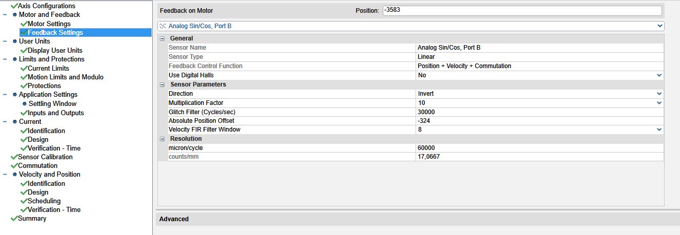
The integrated encoder is a SIN/COS 1Vpp connected to Port B of the drive (here the drive is Gold DC Bell), with a sine period corresponding to 60 mm of pole pitch (NL120Q).
Current Limits
Current Identification
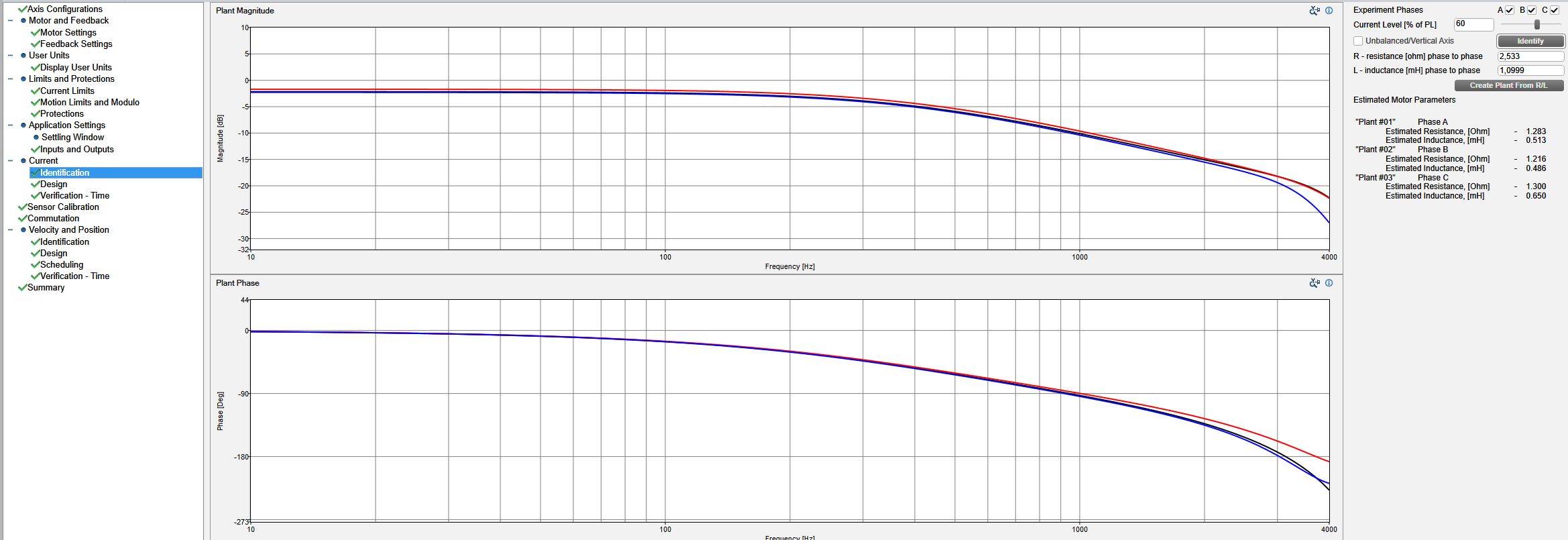
Perform current identification by pressing the Identify button at the top right of the window. The drive calculates the phase resistance and inductance of the single phase. The resulting values are the original phase-to-phase resistance and inductance divided by a factor of 2.
Current Design
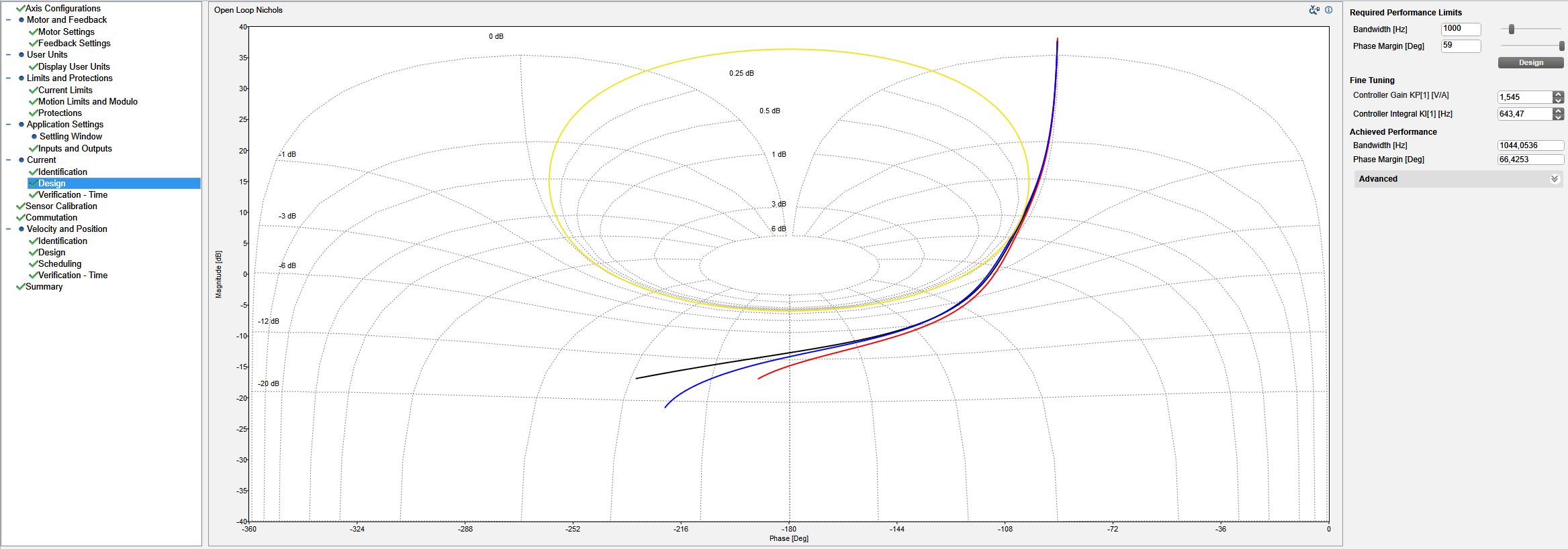
Press the Design button at the top right of the window to calculate the current loop parameters.
Current Verification - Time
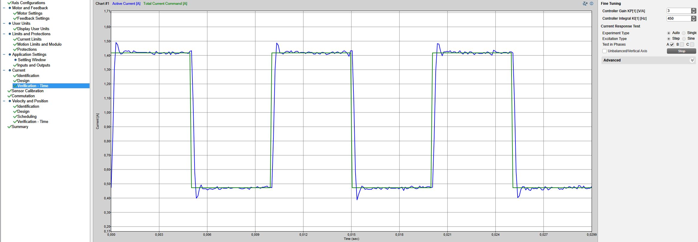
Click the Start button at the top right of the window to start the verification. The drive injects a square wave into the current loop. Change the controller gain and integral values so that the response is close to the injected square wave profile (green). The target is minimum overshoot and maximum slope on the current feedback signal (blue).
Sensor Calibration
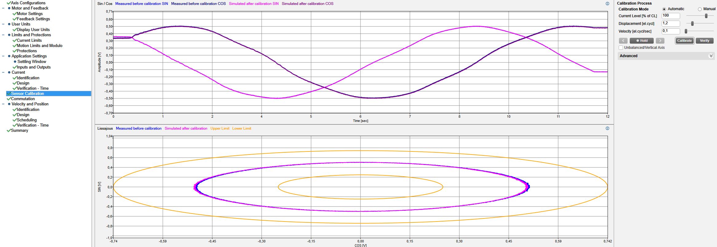
Specify the correct displacement for this calibration, typically at least one sine period ⇒ Displacement [el.cycl] = 1.2. Then move the slider to a position that avoids the mechanical stop interaction. With 1.2 on the displacement, the motor moves forward and backward over the motor pole pitch × 1.2 = 60 × 1.2 = 72 mm. When the motor is in the right position, press the Calibrate button.
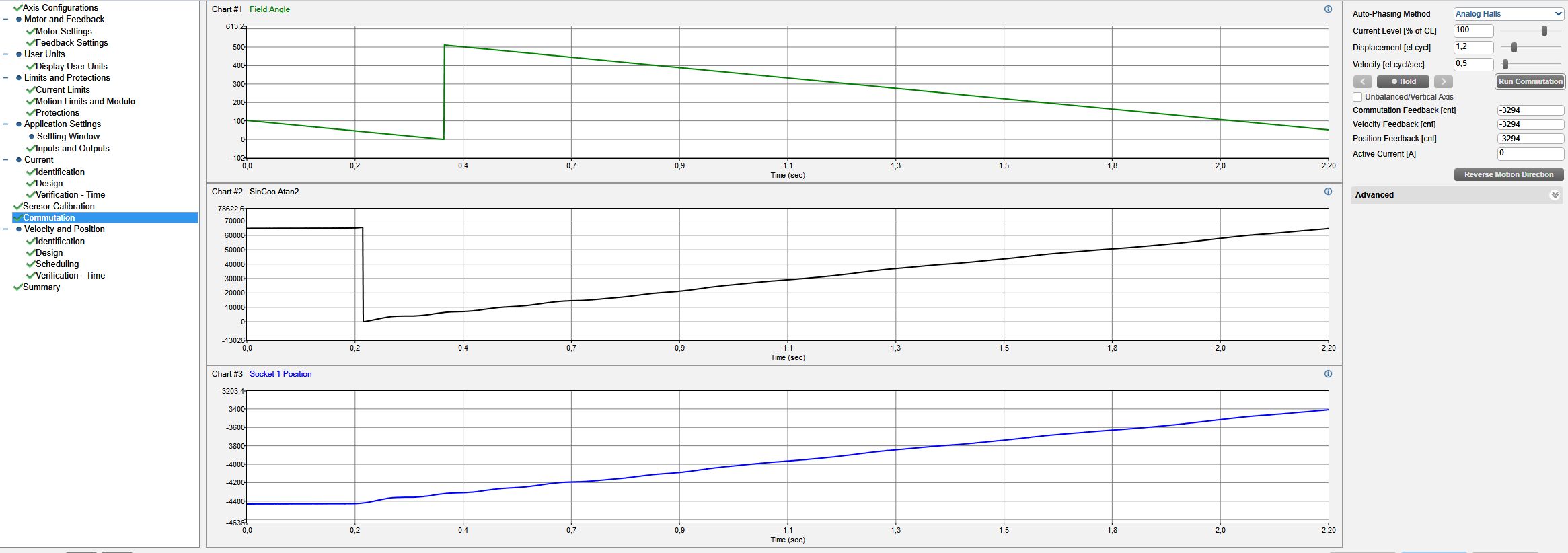
Motor commutation
To calculate and store the commutation offset, move the slider to a position that avoids the mechanical stop interaction and press the Run commutation button at the top right of the window. The slider moves over a span of 1.2 × pole pitch = 1.2 × 60 = 72 mm (the span can be reduced using the Displacement [el. cycl] parameter).
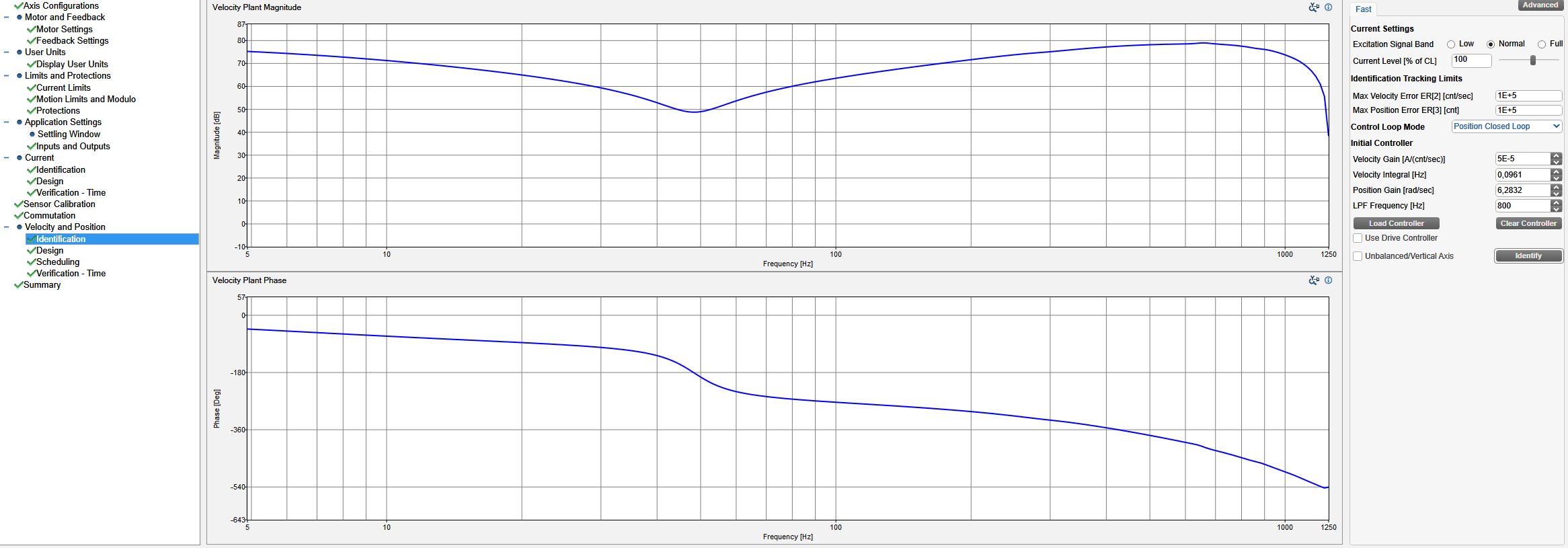
Velocity and position identification
Perform a verification by setting the control loop mode to Position Closed Loop, with a low-pass filter value of 800 Hz (typical value for NL120).
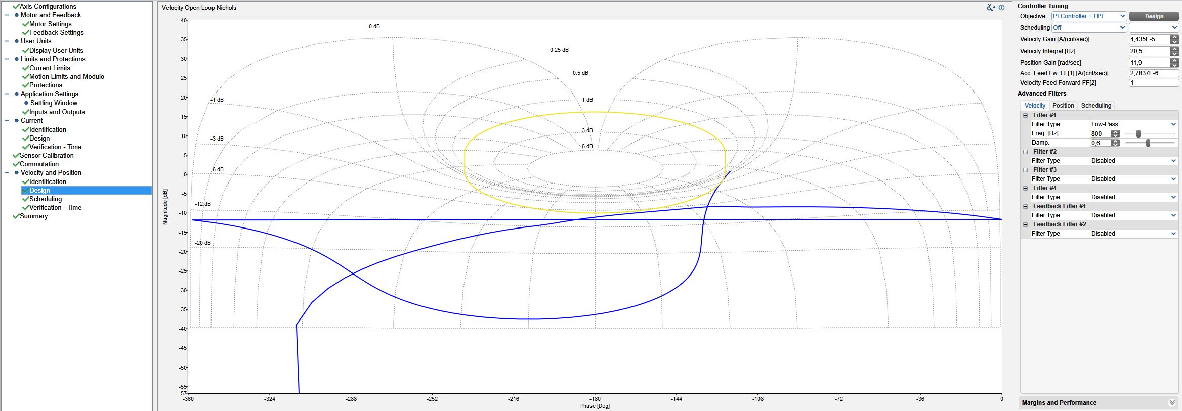
Velocity and position design
Press the Design button to calculate the position and velocity values. Normally, the velocity integral must be increased to increase the stiffness of the slide. Enable the motor and increase the value to achieve slider rigidity. Typically 500 Hz of velocity integral is needed.
Velocity and position verification - Time
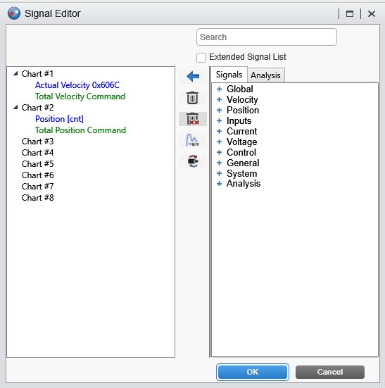
To fine-tune the motor, use the Verification time window, injecting a sine wave on the position loop corresponding to at least 300 counts, with a frequency of 1.2 Hz (for example). See the results on the position command/position feedback and speed command/speed feedback signals. The oscilloscope settings are a resolution of 800 µs with a record time of 2.183 s.
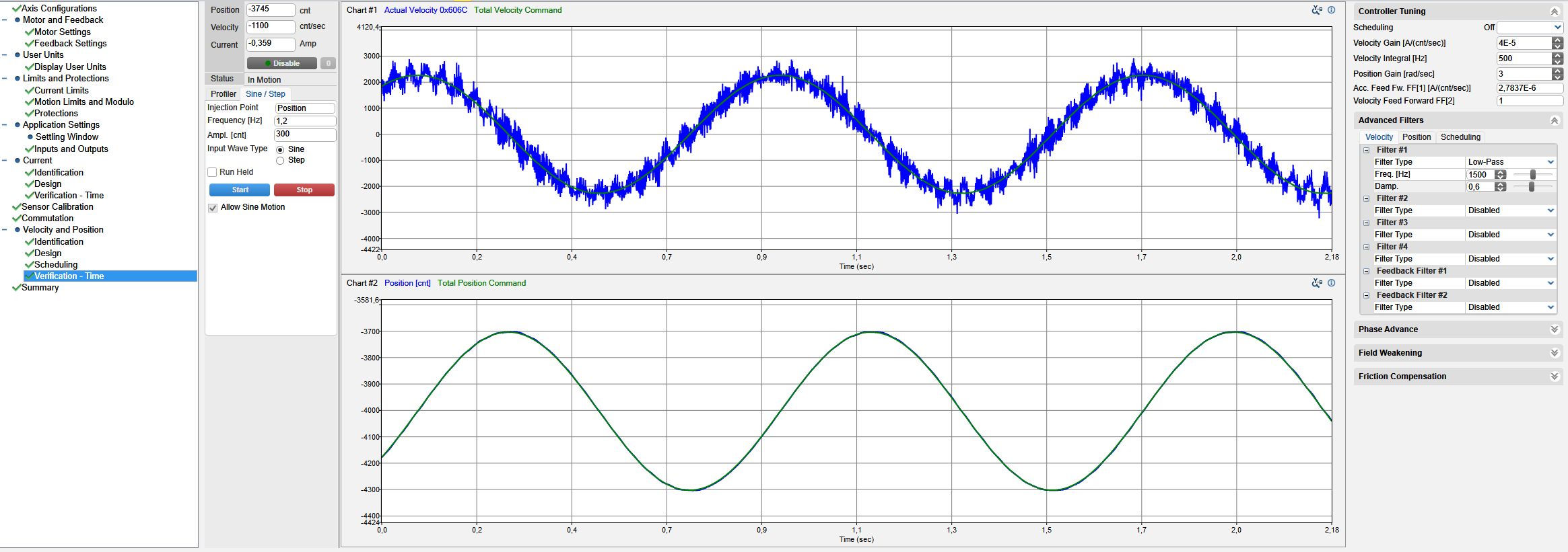
The typical values for NL120Q are: :miniature_motors:nl120q_elmo_dcbell.zip
Velocity gain [A/count/sec] = 4E-5
Velocity integral [Hz] = 500
Position gain [rad/sec] = 3
Acceleration feed FW [A/count/sec] = 2.78E-6
Velocity Feedforward FF[2] = 1
Low pass filter Freq. [Hz] = 1500
Damping factor = 0.6